Robbin B. Sotir & Associates, Inc.
"Stabilization of High Soil and Rock Cut Slope by Soil Bioengineering and Conventional Engineering"
TRANSPORTATION RESEARCH RECORD NO. 1589
Soils, Geology, and Foundations
Variable Tire Pressure, Flowable Fill, Dust Control, and Base and Slope Stabilization
A peer-reviewed publication of the Transportation Research Board
Transportation Research Board National Research Council
NATIONAL ACADEMY PRESS WASHINGTON, D.C. 1997
All rights reserved.
Robbin B. Sotir and Michael A. McCaffrey
Construction of a 274.5-m-long (900 ft) and 24.4-m-high (80 ft) soil (upper) and rock (lower) cut slope on the eastbound side of the Massachusetts Turnpike at mile mark 94.1 eastbound for the proposed interchange with Route 146 combined conventional engineering and soil bioengineering solutions. Geologic mapping identified three sections (east, middle, and west) that had different patterns of rock discontinuities, which controlled rock cut design. Each required a different slope design for a stable rock cut. The soil cut design was controlled by soil density, groundwater seepage, and erosion potential from seepage and surface runoff. Soil bioengineering was used to control surface drainage and erosion on the cut soil slope above the 12.2-m-high (40 ft) rock cut and rapidly revegetate the disturbed soil slope, which addressed the project's environmental and aesthetic goals. Conventional crushed-stone drains augment the living soil bioengineering drains. Woody vegetation was used to reinforce the cut soil slope surface. Branches from native living woody plants were installed into the slope face offering surface reinforcement. Root development along branch lengths provided additional reinforcement. The hydrologic regime was modified as growing plants remove moisture through transpiration and embedded bundled branches channel water off the slope. Basic soil bioengineering stabilization principles by using live fascines and brush layers for soil and rock cut slope stabilization are presented. Discussions include pre-construction conditions, environmental benefits, vegetation harvesting and design, installation and performance as of October 1996. Cut slope stabilization through soil bioengineering produced an environmentally, aesthetically and mechanically sound solution, illustrating the benefits of combined technologies.
The construction of a new interchange between the Massachusetts Turnpike and Route 146 in Millbury, Massachusetts, required widening of the Turnpike at Mile 94.1 eastbound at an existing soil and rock slope 24.4 m (80 ft) high. A section of the existing slope 274.5 m (900 ft) long needed to be cut back up to 8.23 m (27 ft) to accommodate the proposed on-ramp. GEI Consultants, Inc., and Robbin B. Sotir & Associates Inc. were responsible for developing a design for stabilization of the proposed soil and rock cut for the Massachusetts Turnpike Authority (MTA). The final design documents were prepared by Peter Cavicchi and Karina Bartelmann of the MTA. Ronald Dionne and Dale Morse of the MTA managed the construction work. Vollmer Associates of Boston was the lead design consultant for the project, including the on-ramp.
The engineering and soil bioengineering design and installation work along a 274.5 m (900 ft) section of roadway are documented in this paper. The project goals were to improve drainage, protect against slope failure, control soil erosion and revegetate and restore the soil slope.
PRECONSTRUCTION SITE CONDITIONS
Rock Slope
The geology of the existing rock cut was studied to evaluate characteristics that would affect the stability of the proposed rock cut. The rock is composed of schist, gneissic schist, and schistose gneiss, with the more gneissic rock toward the west. The eastern 30.5 m (100 ft) section of the rock cut was severely weathered, and there were also several bands of badly weathered rock throughout the cut. Some of the weathering bands followed joints and shear zones. The remainder of the cut was moderately to slightly weathered.
Joints along the foliation are the dominant discontinuities and often traverse the cut from toe to crest. Other minor joint sets were identified. A rock wedge failure of about 19.12 m3 (25 yd3) occurred in March 1995 along the intersection of two joints, one of which was a foliation.
Soil Slope
Before construction, the project area was a soil and rock cut 24.4 m (80 ft) high, transitioning into a 2H:1V (H, horizontal: V, vertical) cut soil slope to the east of the project area. The soil at the site is dense glacial till consisting mostly of silty sand with gravel and ranging from 1.52 m (5 ft) to 15.25 m (50 ft) thick. A thin layer of topsoil partially covered the site.
There was an existing subsurface drainage system made up of polyvinyl chloride pipe and crushed stone, which appeared to have controlled most of the seepage problems. An exception to this was a soil slough, which developed in 1994 at mid-height on the far eastern end of the site, where significant seepage was observed (see Figure 1).
The northern slope orientation and active seepage areas result in very wet conditions on the slope, as the sun has less of a drying effect on the soil. The soil temperatures are also lower than on slopes with different orientations, so the frozen soil thaws later in the spring. Conversely, in times of drought, this slope remains cooler and moister than others do. Although this reduced solar exposure is not optimum for some types of vegetation, it was expected to be adequate for successful growth. Before construction, the slope was vegetated with a mixture of grasses and herbaceous plants and a limited number of woody species. Exposed soil with no vegetative cover was especially evident in wet areas.
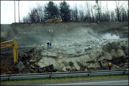 Figure 1 Shallow slope failure caused by seepage conditions before rock/soil excavation (east-end of project site).
ROCK SLOPE DESIGN
Discontinuities in a rock mass significantly decrease the strength normally associated with an intact mass. This loss of strength requires that exploration and design focus on the inhomogeneous nature of the rock.
Data obtained in the geologic reconnaissance were used to evaluate the stability of the proposed rock cut and to develop the final design slope of the rock cut. The design slope angle was controlled by the discontinuities and needed to be compatible with the dip of the discontinuities. In the eastern section of the cut, where the strike of the foliation joints parallels the rock cut, a rock-cut slope angle equal to or shallower than the dip of the joints was necessary to prevent sliding failures along the foliation. A 1H:1V slope was chosen for this area, as indicated in Figure 2. In the western half of the cut, the strike of the foliation joints is at an angle to the strike of the cut and few intersecting joints were observed that would cause unstable wedges. The design slope of the rock cut was controlled by the potential for unstable wedges that daylight in the face of the cut. A 0.25H:1V slope was chosen for this section.
Even a well designed and constructed rock cut is susceptible to rockfall over time because of gravity and ice-wedging forces. A toe ditch was designed at the base of the rock slope to dissipate the vertical and lateral momentum of the rockfall and to collect rockfall and prevent it from landing in the roadway, as indicated in Figure 2. Water runoff is collected in a crushed-stone drain at the base of the rock cut and discharged.
A bench 1.83 m (6 ft) wide was created at the top of the rock cut to provide a buffer zone between the rock cut and soil cut, as indicated in Figure 2. The bench is the top of the existing rock and it was made by removing the soil cover and starting the toe of the soil cut 1.83 m (6 ft) back from the top of the rock cut. The rock bench is intended to prevent undermining of the soil cut if the rock face overbreaks or if, during construction, the top of the rock dips unexpectedly. Such a dip would collect soil, cobbles, and boulders that erode from the soil cut during construction and might create a rockfall.
 Figure 2Typical rock and soil cut section
ROCK SLOPE CONSTRUCTION
Perimeter control of the rock excavation was achieved with cushion blasting. This control was necessary to minimize damage to the final rock face and to produce a planar cut.
The upper 3.05 m (10 ft) of rock in the 45.75-m-long (150 ft) middle section of the cut was severely weathered. Small blocks were raveling from this zone, and with time this process would have undermined the soil slope above it. To prevent long-term stability problems, this section of weathered rock was cut back to a slope of 1H:1V. The soil slope was cut back to accommodate the new location of the rock bench at the crest of the rock cut.
A boulder wall 6.1 m (20 ft) high was constructed along the full height of the rock cut near the eastern end to stabilize severely weathered rock that had failed during construction.
SOIL CUT
A slope of 2H:1V was chosen for the soil cut, as indicted in Figure 2. The eastern end of the soil cut had a history of significant groundwater seepage problems, and a large slough was observed during site visits before design (Figure 1). Drains constructed of pipe and crushed-stone drains wrapped in geotextile were installed to collect the seepage and channel it away from the rock cut. Three lateral drains were installed about 1.22 m (4 ft) below the surface along the top, middle, and bottom of the eastern half of the soil cut. The laterals slope slightly toward a central collector drain, which extends straight down the soil slope, under the boulder wall, and discharges into the toe ditch drain at the base of the rock cut.
A soil berm was constructed at the crest of the soil cut to prevent surface water runoff from entering the cut. A large forested and wetland area slopes toward the top of the cut and provides a significant recharge area for groundwater and surface-water runoff. It is likely that this recharge area is the source of the groundwater observed seeping from the soil slope, particularly in the eastern section. The random locations of the seepage observed in the soil slope may be from more pervious (sandy) lenses of soil in the glacial till that intersect the cut and drain more rapidly.
SOIL BIOENGINEERING METHODS AND DESIGN APPROACH
Soil bioengineering utilizes mechanical, hydrological, biological, and ecological concepts to develop living structures used in the stabilization and revegetation of slopes. Living woody plant material forms the main reinforcing component of these systems.
The soil bioengineering system was designed to respond to the specific site conditions. Analysis revealed that some areas of the slope are especially wet, which increases the possibility of erosion and slope failure. The wetter areas of the slope were longer and steeper between stations 775 + 00 and 778 + 50. For these areas a series of herringbone installations was proposed (Figure 3). These living herringbone systems are typically very effective in draining a slope by intercepting water (both subsurface and surface) and functioning as a drain. Drainage is also improved through evapotranspiration and internal drainage as the plants root and develop leaves. In the relatively drier areas of the site, from station 769 + 50 to 774 + 75, live fascine and brush layer/live fascines were used without a central pole drain.
Figure 3
Face view (perpendicular view) of slope above rock cut and lower pole drain.
The soil bioengineering system installed on this project is intended to provide the following benefits. Mechanically, the stems and root system of the plant material protect the soil against erosion and shallow slope failure. The roots function as fibrous inclusions, reinforcing the soil mantle and increasing the resistance to sliding. Slope instability and erosion are reduced by transpiration of moisture and interception of rainfall. Hydrologically, the system improves drainage and controls seepage. The stems, leaves and surface litter add roughness, which retards overland flow. Ecologically, the pioneer plants that are used enhance the wildlife habitat. Biodiversity is increased as vegetative invasion and natural succession occur, creating self-sustaining native plant communities.
INSTALLED SOIL BIOENGINEERING METHODS AND SYSTEMS
Herringbone System
This system is composed of a series of laterals (live fascines and brush layer/live fascines) arranged in a specific herringbone pattern along a central pole drain (see Figures 4 - 6). These laterals, angled downslope, connect and drain into the central pole drain, which is connected to the lower pole drain at the toe of the soil slope just above the rock face. This system was used in the wet eastern areas of the site. In the drier areas, a central pole drain was not used and the laterals connect directly into the lower pole drain (Figure 5). Descriptions of the individual methods that make up the herringbone system are described in the following section.
Figure 4
Herringbone system and detail bundles used for top, central, and lower drains.
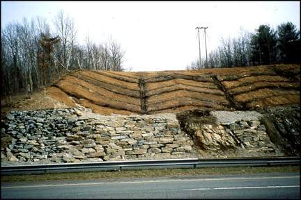
Figure 5
Herringbone system used to drain wet areas in eastern slope section, immediately after construction.
Some of these methods are also used independently on drier areas of the site without central pole drains.
Top, Central, and Bottom Pole Drain
These systems comprise three bundles grouped together (Figure 4). The large fascine on the bottom is not intended to grow and is installed mainly for drainage. The two live fascines installed on top are expected to grow. Together the three bundles are intended to function as a drain. In addition, their root systems and leaves reinforce the soil and protect against surface erosion.
Central pole drains are installed from the top to the bottom of the slope, and the top and lower pole drains are placed approximately parallel to the roadway and at a gentle downslope gradient. They are mainly intended to transport water from the face to the lower pole drain.
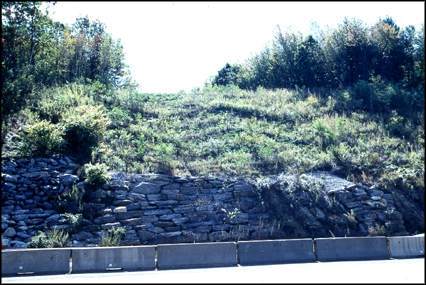
Figure 6
Growing herringbone system during the second year.
Live Fascine
A live fascine is a collection of live, cut branches, fabricated into a bundle (Figure 7). This bundle is placed in a prepared coir-lined (woven coconut) trench and secured. Live fascines are intended to provide immediate mechanical reinforcement and erosion control and will eventually root and provide additional reinforcement of the surface soil mantle. They are used here as laterals in the herringbone system and as laterals draining directly into the lower pole drain.
Brush Layer/Live Fascine
The brush layer/live fascines are composed of branches placed on terraces cut into the slope. The brush is placed approximately perpendicular to the slope with the growing tips oriented out. A live fascine is then installed on top of the brush layer (Figures 8 and 9).
This method typically provides immediate erosion control, because the live fascines and dense brush slow runoff, trap debris and reduce surface erosion. Unrooted branch stems offer immediate shallow reinforcement to the soil. The roots, stems, and leaves that are expected to develop will offer additional soil reinforcement and surface protection. The orientation of this installation, angled down the slope, allows it to immediately function as a drain, helping to collect and channel surface-water runoff and groundwater seepage down the slope.
Harvesting, Handling, and Storage of Cuttings
The harvesting of biotechnically suitable plant material (pioneer plants such as willow and dogwood that root readily from cuttings) and installation need to be carefully planned and coordinated. Before construction, harvest sites were selected based on species mix, quantity, age and quality of material, site access, and proximity to the project site.
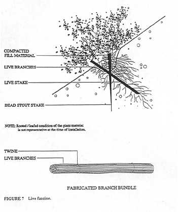
Figure 7
Live fascine
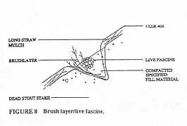
Figure 8
Brush layer/live fascine
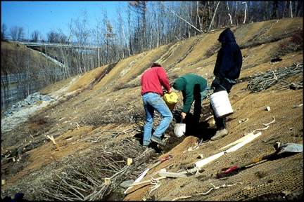
Figure 9
Installation of live fascine in herringbone system
CONCLUSIONS
The initial soil bioengineering installation improved drainage, shallow mass stabilization and erosion control aesthetics and has enhanced habitat values. Figures 10 through 12 present comparisons of the site during construction, immediately afterward, and in the first growing season.
The key elements of success in this soil bioengineering-engineering combination include a stable rock cut with an adequate factor of safety against a deep-seated failure and collection and proper channeling of surface and groundwater seepage from the site. Also required is immediate control of erosion to prevent surface sloughs and failures and to improve the natural invasion of the surrounding plant community. To date, the project has been successful in fulfilling the long-term mechanical and ecological goals of the project.
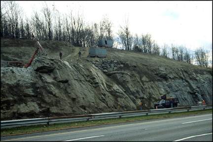
Figure 10
During construction
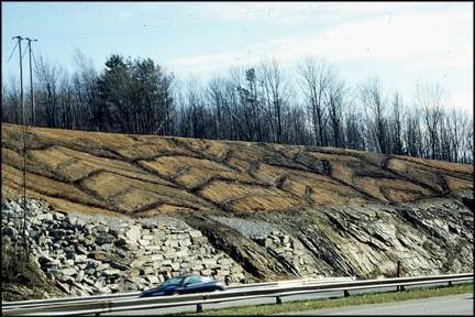
Figure 11
Immediately after construction
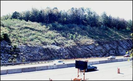
Figure 12
During second growing season
3221 Stoney Acres Drive
Kennesaw, Georgia 30152
Phone: 770-424-0719
sotir@sotir.com
©2020 Robbin B. Sotir & Asociates, Inc.